KS0251 Keyestudio 4-channel Relay Shield

Introduction
The keyestudio relay shield has integrated a 4-channel 5V relay module, which is fully compatible with UNO R3 control board.
The 4-channel relay on the shield is active at HIGH level. Separately connect the 4-channel relay to the digital port 4, 5, 6, 7 on the UNO R3 board, then through controlling output HIGH or LOW to control the relay on and off.
Features:
The relay shield is 5V active HIGH
Contact capacity: AC120V / 3A ; DC24V/3A
Onboard LED indicator for relay output status
Indicator: 4 LEDs are red when the relay is driven high, the corresponding indicator will light up.
Standard interface can be directly connected with microcontrollers.
Fully compatible with UNO R3 board
Be able to control various appliances and other equipment with large current.
3 M3 screw positioning holes for easy installation
Power Interface: 5V DC power interface
Channel: 4 channel
PCB Color: Black
Details:
Size: 69mm*54mm*26mm
Weight: 39.4g

PINOUTS:
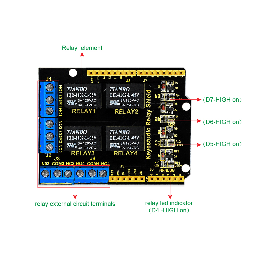
Relay Terminals:
Terminal high-power, high-current high voltage can be connected to the device.
When D4 is High, RELAY 4 turns on, LED4 lights up, COM4 and NO4 connected, COM4 and NC4 disconnected.
If D4 is LOW, RELAY 4 turns off, LED4 not light, COM4 and NO4 disconnected, COM4 and NC4 connected.
When D5 is High, RELAY 3 turns on, LED3 lights up, COM3 and NO3 connected, COM3 and NC3 disconnected.
If D5 is LOW, RELAY 3 turns off, LED3 not light, COM3 and NO3 disconnected, COM3 and NC3 connected.
When D6 is High, RELAY 2 turns on, LED2 lights up, COM2 and NO2 connected, COM2 and NC2 disconnected.
If D6 is LOW, RELAY 2 turns off, LED2 not light, COM2 and NO2 disconnected, COM2 and NC2 connected.
When D7 is High, RELAY 1 turns on, LED1 lights up, COM1 and NO1 connected, COM1 and NC1 disconnected.
If D7 is LOW, RELAY 1 turns off, LED1 not light, COM1 and NO1 disconnected, COM1 and NC1 connected.
Hookup Guide
Simply stack the shield on the UNO board.

Sample Code
How to download and install Arduino IDE and driver.
Click here to download the code or directly copy the code below to IDE.
**************************************************************************
int BASE = 4 ; //The first relay is connected to the I / O port
int NUM = 4; //Total number of relays
void setup()
{
for (int i = BASE; i < BASE + NUM; i ++)
{
pinMode(i, OUTPUT); //Set the number I/O port to outputs
}
}
void loop()
{
for (int i = BASE; i < BASE + NUM; i ++)
{
digitalWrite(i, LOW); //Set the number I/O port outputs to “low”, that is, gradually turn off the relay.
delay(200); //delay 0.2S
}
for (int i = BASE; i < BASE + NUM; i ++)
{
digitalWrite(i, HIGH); //Set the number I/O port outputs to “high”, that is, gradually turn on relay.
delay(200); //delay 0.2S
}
}
**************************************************************************
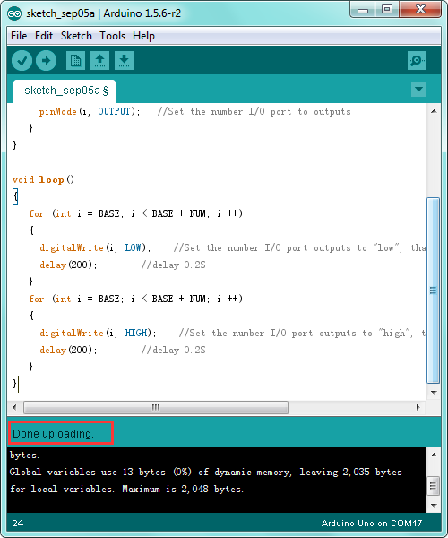
Test Result
Done uploading the above code, you should see the 4-channel relay is first connected, and then disconnected one after another, repeatedly.

Resource Links