KS0184 keyestudio Multi-purpose Shield V2

Description
Multi-purpose Shield V2 is a learning board based on Arduino. No need for soldering and connection. Download the program to complete experiment.
It is multi-purpose and we offer code libraries of all modules that have been tested. You can use them directly.
There are extension ports on the shield to help you to complete other experiments.
Features
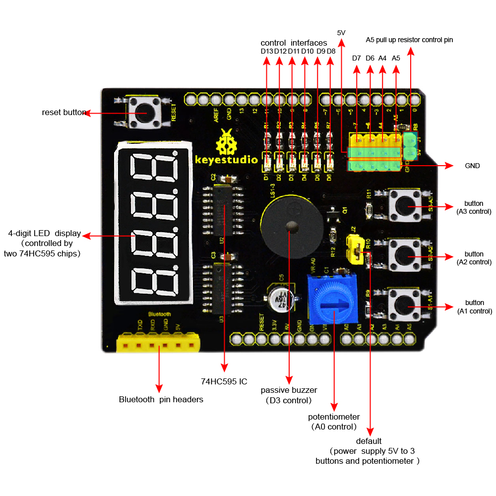
Compatible with main controllers such as UNO R3 and MEGA.
Comes with 6 LED indicators to show the program status.
Comes with 3 switching buttons
Comes with a reset button
Comes with a potentiometer for analog input
Comes with a passive buzzer for alarm.
Comes with a 4-digit LED display to show the number
Details
Dimensions: 68mm*54mm*19mm
 Weight: 23g
Interface Instruction
Hookup Guide
Simply plug the shield into UNO R3 board or MEGA.

Upload the Code
You can click here to download the code or directly copy the code below to Arduino software.
***************************************************************************************
//pressing nothing to display value of analog revolving potentiometer
//pressing key1 to show 0-3 on LED Segment Displays
//pressing key2 and buzzer ringing
//pressing key3 and flowing light on
//defining three pins of 74HC595
int latchPin = 4;//ST_CP
int clockPin = 5;//SH_CP
int dataPin = 2; //DS
//defining three key input
int key1 = A1;
int key2 = A2;
int key3 = A3;
//buzzer pin
int buzzer = 3;
//pin definition of flowing light
int led1 = 13;
int led2 = 12;
int led3 = 11;
int led4 = 10;
int led5 = 9;
int led6 = 8;
int dat_wei[4]={0x01,0x02,0x04,0x08}; //LED Segment Displays
//showing 1–4
int dat_duan[10]={0xc0,0xf9,0xa4,0xb0,0x99,0x92,0x82,0xf8,0x80,0x90}; //LED Segment Displays showing 0–9
char i=0;
void setup ()
{
pinMode(latchPin,OUTPUT);
pinMode(clockPin,OUTPUT);
pinMode(dataPin,OUTPUT);
pinMode(key1,INPUT);
pinMode(key2,INPUT);
pinMode(key3,INPUT);
pinMode(buzzer,OUTPUT);
pinMode(led1,OUTPUT);
pinMode(led2,OUTPUT);
pinMode(led3,OUTPUT);
pinMode(led4,OUTPUT);
pinMode(led5,OUTPUT);
pinMode(led6,OUTPUT);
for(char i=8;i<14;i++)
digitalWrite(i,HIGH);
}
void loop()
{
if(digitalRead(key1)==LOW )
SMG(); //testing LED Segment Displays
if(digitalRead(key2)==LOW )
buzzer_(); //testing buzzer
if(digitalRead(key3)==LOW)
led_display(); //testing LED
if(digitalRead(key1)==HIGH & digitalRead(key2)==HIGH & digitalRead(key3)==HIGH)
analog(); //testing analog input
}
void SMG(void)
{
digitalWrite(latchPin,LOW); //clear LED Segment Displays
shiftOut(dataPin, clockPin, MSBFIRST ,0x00);
shiftOut(dataPin, clockPin, MSBFIRST ,0x00);
digitalWrite(latchPin,HIGH);
while(1)
{
digitalWrite(latchPin,LOW);
//MSBFIRST,transmitting binary bit from high to low,74HC595 starts from first piece, and displaces data from Q0 to Q7. If there is data, it will start from the second piece like this.
shiftOut(dataPin, clockPin, MSBFIRST ,dat_duan[i]); //data about second piece
shiftOut(dataPin, clockPin, MSBFIRST ,dat_wei[i]); //way of MSBFIRST,data about first piece
digitalWrite(latchPin,HIGH);
i++;
if(i==4){i=0;}
if(digitalRead(key1)==HIGH)
{
digitalWrite(latchPin,LOW); //clear LED Segment Displays
shiftOut(dataPin, clockPin, MSBFIRST ,0x00);
shiftOut(dataPin, clockPin, MSBFIRST ,0x00);
digitalWrite(latchPin,HIGH);
break;
}
}
}
void buzzer_(void)
{
char i;
digitalWrite(latchPin,LOW); //clear LED Segment Displays
shiftOut(dataPin, clockPin, MSBFIRST ,0x00);
shiftOut(dataPin, clockPin, MSBFIRST ,0x00);
digitalWrite(latchPin,HIGH);
while(1)
{
for(i=0;i<80;i++)// output a frequency sound
{
digitalWrite(buzzer,LOW);// sound
delay(1);//delay1ms
digitalWrite(buzzer,HIGH);//not sound
delay(1);//ms delay
}
for(i=0;i<100;i++)// output a frequency sound
{
digitalWrite(buzzer,LOW);// sound
digitalWrite(buzzer,HIGH);//not sound
delay(2);//2ms delay
}
if(digitalRead(key2)==HIGH)
{
digitalWrite(latchPin,LOW); //clear LED Segment Displays
shiftOut(dataPin, clockPin, MSBFIRST ,0x00);
shiftOut(dataPin, clockPin, MSBFIRST ,0x00);
digitalWrite(latchPin,HIGH);
break;
}
}
}
void led_display()
{
digitalWrite(latchPin,LOW); //clear LED Segment Displays
shiftOut(dataPin, clockPin, MSBFIRST ,0x00);
shiftOut(dataPin, clockPin, MSBFIRST ,0x00);
digitalWrite(latchPin,HIGH);
while(1)
{
digitalWrite(led1,LOW);
delay(100);
digitalWrite(led1,HIGH);
digitalWrite(led2,LOW);
delay(100);
digitalWrite(led2,HIGH);
digitalWrite(led3,LOW);
delay(100);
digitalWrite(led3,HIGH);
digitalWrite(led4,LOW);
delay(100);
digitalWrite(led4,HIGH);
digitalWrite(led5,LOW);
delay(100);
digitalWrite(led5,HIGH);
digitalWrite(led6,LOW);
delay(100);
digitalWrite(led6,HIGH);
if(digitalRead(key3)==HIGH)
{
break;
}
}
}
void analog()
{
int val,qian,bai,shi,ge;
val=analogRead(A0);
qian=val/1000;
bai=val%1000;
bai=bai/100;
shi=val%100;
shi=shi/10;
ge=val%10;
digitalWrite(latchPin,LOW);
shiftOut(dataPin, clockPin, MSBFIRST ,dat_duan[qian]);
shiftOut(dataPin, clockPin, MSBFIRST ,0x01);
digitalWrite(latchPin,HIGH);
digitalWrite(latchPin,LOW);
shiftOut(dataPin, clockPin, MSBFIRST ,dat_duan[bai]);
shiftOut(dataPin, clockPin, MSBFIRST ,0x02);
digitalWrite(latchPin,HIGH);
digitalWrite(latchPin,LOW);
shiftOut(dataPin, clockPin, MSBFIRST ,dat_duan[shi]);
shiftOut(dataPin, clockPin, MSBFIRST ,0x04);
digitalWrite(latchPin,HIGH);
digitalWrite(latchPin,LOW);
shiftOut(dataPin, clockPin, MSBFIRST ,dat_duan[ge]);
shiftOut(dataPin, clockPin, MSBFIRST ,0x08);
digitalWrite(latchPin,HIGH);
}
***************************************************************************************
Test Result
Done uploading the code to the board, power on the board, you should see the 4-digit LED display the number. Shown below.

The analog value output by potentiometer is showed on the 4-digit LED display. Press the button S3-A3, the 6 SMD LEDs will light up one by one like the flowing light, but 4-digit LED display is off.
Press the button S2-A2, the passive buzzer will beep and 4-digit LED display is still off.
Press the button S1-A1, 4-digit LED display will show the default number 0123.
Resource: